
The use of fluid power is widespread in many stationary and mobile applications. Many of the operators, technicians, and engineers are not well-versed in the operational, maintenance, and safety aspects of fluid power. Therefore, systematic training is essential for them to handle fluid power systems.
Modern hydraulic technology can be used to make the brakes in cars work, help aeroplanes to climb and turn, and steer and stabilize giant ocean liners. Hydraulic applications have sprung up in a wide variety of areas in the last few decades. Today we can see many examples of hydraulic technology in use all around us. Some of the typical hydraulic applications are highlighted below:
1. Hydraulic Press
The primary function of a hydraulic press is to convey force and/or motion to its tool and die section for forming or blanking workpieces. The press uses a hydraulic pump and a large-volume cylinder for power transmission and work operations. It is controlled by fast-acting valves for superior performance. It also incorporates interlocking and barrier guards for safeguarding the equipment and personnel. Modern presses are capable of configuring work parameters such as the travel distance and the amount of force.

Industrial Hydraulic Systems and Circuits – Basic Level in the SI Units
Joji Parambath
Industrial Hydraulics – Basic Level in the English Units
Joji Parambath
For more details, please visit the website: https://jojibooks.com
2. Hydraulic Work Holding Systems
Hydraulic work-holding systems are used to perform the positioning and clamping functions of workpieces. They are suitable for applications ranging from the simplest fixture to more complex robot-assisted machining centres. Linear cylinders, clamping cylinders, and support cylinders are employed in hydraulic work-holding systems for the positioning and precise support of workpieces. Hydraulic clamping is less time-consuming than mechanical clamping. The use of a hydraulic work-holding system reduces the cycle time, thereby increasing the manufacturing capacity and reducing the costs. It is preferable in high-volume applications, or when critical tolerances need to be held. However, it is costlier than a comparable mechanical clamping system.
3. Plastic Injection Moulding Machine
A plastic injection moulding machine has an injection section and a mould section. The injection section consists of a barrel, a screw, a heater, a nozzle, and hydraulic actuators for plasticizing solid raw plastic and injecting. The mould section performs the clamping and moulding operations. The machine operates on a four-step cycle: (1) plasticizing solid raw plastic, (2) closing mould and clamping, (3) injecting the plastic, and (4) opening the mould.
A screw rotating inside the barrel shears and heats the granular raw plastic and softens it to the plastic (gently flowing) state. This operation usually involves a low-speed, high-torque (LSHT) hydraulic motor. The clamping arrangement for the mould has moving and fixed platens. These platens hold the mould tool together under pressure. The gently flowing plastic is then injected into the mould under pressure. Hydraulic cylinders are used for clamping the mould and injection of the plastic material into the mould.
4. Hydraulic Excavator
It is a piece of heavy construction equipment operating similar to a combined human arm and hand. It is used to dig and move large objects. It consists of three parts: (1) a set of working elements, (2) an upper structure, and (3) a lower structure.

The working part consists of a boom, an arm, and a bucket, which are powered by hydraulic cylinders. The boom provides the arm’s up-and-down movements. The powerful arm with the bucket attachment is designed for digging, lifting, and loading soil. The bucket, with hardened side cutters and teeth, is used to dig or break hard soil and rocks.
The hydraulic system in the excavator typically consists of three pumps that are driven by its engine. The third pump supplies fluid to its pilot control circuits at low pressures ranging up to 50 bar [700 psi]. Joysticks are provided to control the bucket and boom assembly movement and the upper structure rotation. A boom suspension circuit for the wheeled excavator can be incorporated to smooth out the bounce of the loaded bucket during its transport through rugged terrains. Many of the control solutions for the excavator can easily be achieved through the use of cartridge valves and manifolds.
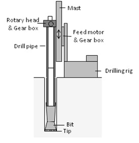
5. Drill Rigs
A rig is a machine used to drill wells and it provides a means for discovering hidden energy reserves. It consists of a drilling system, a feed system, and a propulsion system. The rig is mounted on an undercarriage. The drilling system makes holes for oil or mineral exploration. The feed unit moves the drill unit up and down. A propulsion system runs the undercarriage. The required movements of the drill unit, feed unit, and propulsion system are hydraulically actuated and controlled.
References: (1) Industrial Hydraulic Systems and Circuits -Basic Level in the SI Units, (2) Industrial Hydraulics -Basic Level in the English Units
Authored by JOJI Parambath, Founder/Director, Fluidsys Training Centre, Bangalore,
email: info@fluidsys.org
web: https://fluidsys.org


")


")


Leave a comment