
The hydraulic system with a load sensing feature provides only the flow and pressure required by the connected load. Controlling both the pressure and the flow allows for a significant reduction in losses, improvement of circuit efficiencies, and enhancement of the system’s service life.
A Typical Load Sensing System
The basic load sensing system typically comprises a variable-displacement load sensing pump, a special compensator, and a load sensing directional control valve with proportional flow characteristics.
Load Sensing Variable-displacement Pump
The flow of the variable displacement pump can be controlled by varying the angle of its swash plate. This type of control can be achieved with the help of the swash plate’s control piston. The pump, along with its compensator, senses and responds to the varying flow and pressure requirements of the associated hydraulic system.
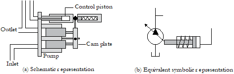
Symbolic representation of a variable-displacement pump
Pump Compensator
The compensator, when connected to a hydraulic system, senses the system’s pressure and flow conditions. It consists of a pressure-flow compensator spool that works against a low-pressure spring {say 20 bar [290 psi] spring} and a high-pressure compensator spool that works against a high-pressure spring {say 300 bar [4350 psi] spring}.
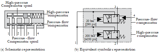
Schematic and symbolic representations of a pump compensator in a load sensing hydraulic pump
Operation of a Load Sensing System
The load sensing system for controlling a hydraulic actuator consists of a variable-displacement pump, a compensator block, and a load-sensing closed-centre directional control valve. The 20 bar [290 psi] spring of the compensator forces the pressure-flow compensator spool towards the left when there is no pressure in the system. This normal spool position allows the fluid to flow directly from the swash plate control piston to the reservoir. As there is no fluid pressure acting on the pump’s control piston, the pump’s camplate is forced to move to its maximum angle position. In this position, the pump is ready to produce the maximum flow.
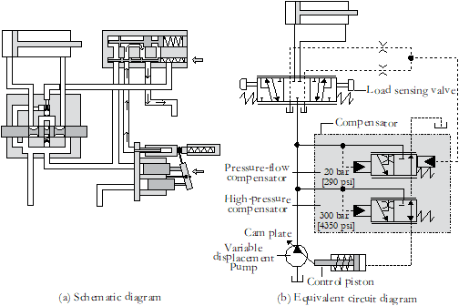
Schematic and symbolic representations of a simple load sensing system in its initial position
When the pump is switched on, the system will slip into the following modes: (1) low-pressure stand-by mode (when the pump is on and the directional control valve is in its centre position), (2) load-sensing mode (when the directional control valve is actuated and load is moving with the requirement of pressure and flow), and (3) high-pressure stand-by mode during its cycle of operation (when the load comes to a stand-still under pressurized condition).
Authored by JOJI Parambath, Founder/Director, Fluidsys Training Centre, Bangalore
Textbook on ‘Load Sensing Hydraulic Systems in the SI Units’
By Joji Parambath
The textbook uses the SI system of units to present information on the classification, constructional features, working, essential terms and definitions, sizing, and safety and maintenance aspects of hydraulic accumulators.
Textbook on ‘Concepts of Load Sensing Hydraulic Systems in the English Units‘
By Joji Parambath
Please click on the image links to go to the Amazon Website


")


")


Leave a comment