
Textbook on ‘Pneumatic Systems and Circuits -Advanced Level’
By Joji Parambath
The textbook presents information on the classification, constructional features, working and essential terms and definitions, sizing, and safety and maintenance aspects of hydraulic accumulators. The book uses the SI system of units.
Please click on the image link to go to the Amazon.com Website
The article ‘How to Develop Multiple-actuator Pneumatic Circuits Using the Cascade Method?’ discussed the basic concepts of the development of multiple actuators. This article explains the Shift Register method with the control task, as given below.
Control Task
A pneumatic circuit has to be developed using the shift register method for realizing the following control task using two cylinders A (1.0) and B (2.0) as shown in Figure 1. The cylinder A is to extend and bring a job under the stamping cylinder B. Cylinder B is then used to extend and stamp the job. Cyclone A can return only after cylinder B has retracted fully.

Figure 1: Schematic diagram for the given control task
Elimination of signal conflicts
Various methods are devised to eliminate the problem of signal conflicts. Most popular methods are based on the ways the air supply to different sections of the control circuit is controlled. Any of the following methods can be used for eliminating the signal conflicts: (1) Cascade method and (2) Shift register. This article explains the Shift Register method.
Shift Register – Design and operating principles
In a shift register 3/2 (or 5/2) memory valves are used in a parallel arrangement as shown in figure 2. The position shown is when signal x4 is applied through a pushbutton valve.
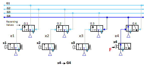
Figure 2: Basic circuit of a ‘shift register’ (4 groups)
The three positions when signal x1, x2 and x3 are applied one after another through the signal elements are shown in figure 3 (a), (b) and (c).
Signal X1 sets the memory valve 0.1, generating output G1, and resets the memory valve 0.4
Signal X2 sets the memory valve 0.2, generating output G2, and resets the memory valve 0.1
Signal X3 sets the memory valve 0.3, generating output G3, and resets the memory valve 0.2
Signal X4 sets the memory valve 0.4, generating output G4, and resets the memory valve 0.3


Figure 3: Different positions of a 4-group shift register.
Solution for the Given Control Task
The Shift register generates output signals one after another for the execution of cylinder actions (A+, B+, B-, and A-) in response to signals from the process. In order to maintain the order of the sequence, each step combines the feedback signal(s) generated by the control actions in the previous stage with the group supply of the previous stage, using an AND valve. For example, to get the supply to group G2, the output signal a1 of the previous group G1 is to be combined with the group G1, using an AND valve. Once a particular stage is set, the previous stage is reset. The pneumatic circuit using shift register for the control task given in the Example is given in the self-explanatory figure.
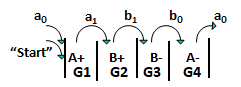
Figure 4: Control scheme of the given control task

Figure 5: Circuit for A+B+B-A-, using Shift register
Step Module
A step module is an integrated circuit with three logic functions: memory, AND and OR. It generates an output signal for executing a movement in the cycle upon receiving a signal from the process and the group signal from the previous module. At the same time, it has the job of resetting the preceding module through the OR valve. However, the technical realization of the module logic varies from manufacturer to manufacturer.
Modular sequencer
The modular sequencer is the backbone of pneumatic sequential automation. The step module is the basic element in the sequencer, which controls a step in the cycle. To complete a given cycle, the sequencer must consist of as many modules as there are steps. The modular sequencer controls each step of the machine operation and receives the corresponding feedback signal. The feedback signal initiates the next step in the cycle, and so on. Figure 6 shows the block diagram of a modular sequencer with four blocks.
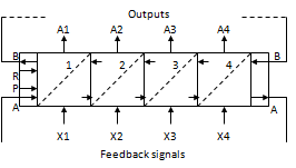
Figure 6: Block diagram of a stepper sequencer
Joji Parambath
Director
Fluidsys Training Centre Pvt Ltd
Bangalore, India
for more articles, please visit:
Fluidsys Training Centre Pvt. Ltd., Bangalore, India
Mob: +917338385505
email: info@fluidsys.org | Website: https://fluidsys.org


")


")


Leave a comment