Hydraulic Power Pack
A hydraulic power pack transforms the power its prime mover conveys to hydraulic power at pressures and flow rates as required for all the system actuators. It is usually a compact, portable, and pre-configured assembly that contains components required to store and condition a given quantity of fluid and push part of the fluid into the system.
Hydraulic Reservoirs
Any hydraulic system requires sufficient high-quality fluid at all times for its efficient operation. The pump draws and pushes the fluid, circulates continuously through various intermediate components to system actuators, and then carries it back to the reservoir. The circulating fluid can accumulate contaminants and absorb heat from the system. Therefore, the fluid must be serviced before it is pumped again into the system.
A well-designed reservoir:
- allows a reasonable dwell time for the fluid,
- allows most of the contaminants to drop out,
- assists in dissipating the heat,
- allows air bubbles to come to the surface and dissipate,
- compensates for the fluid volume changes,
- provides a convenient mounting place for the pump-motor unit and valves.
The reservoir must be located where there is good air circulation for quick heat dissipation. The servicing parts (sight glasses/ filters/ filler breather/ drain cock) must easily be accessible.
Standard Features
A well-designed reservoir should be completely enclosed and self-contained. It may be provided with a filler-cum-breather opening with a suitable air filter, temperature controller, level indicator, and tank heater. The bottom plate of the reservoir is usually inclined from side to side or ‘V’-shaped. A drain plug must be provided at the lowest point of the bottom plate.
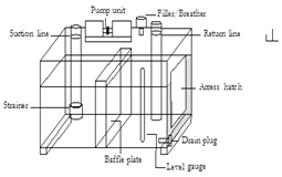
Constructional Features
A typical reservoir is provided with many components, such as:

Baffle Plate
A baffle plate is fitted lengthwise through the middle of the reservoir. Its purpose is to separate the suction chamber from the return chamber. The baffle plate ensures that the return fluid takes a circuitous path through the reservoir, avoiding the same part of the fluid circulating continuously. This also provides more time for the contaminants to settle within the reservoir and assists the reservoir in dissipating heat as quickly as possible.
Suction Line
The suction line is used to carry the fluid to the pump’s inlet. Its bottom end should be located a distance above the bottom floor to prevent the settled contaminants from entering the pump again.
Return Line
The return line is used to carry the return fluid from the system back to the reservoir. The return line must terminate below the fluid level and up to a height two to four times the pipe diameter above the base plate to reduce the turbulence and foaming.
Filler-Breather
The opening provides a path for filling the reservoir during the fluid replacement time. It also allows a passage for the air to breathe in and out of the reservoir during the operating time to equalize the interior and exterior pressures. An air filter of five microns (or better) prevents the ingress of airborne contaminants into the reservoir. The breather may include a quantity of desiccant material (silica gel) to dehumidify the inflowing air.
Strainer/ Suction Filter
A strainer and/or suction filter are fitted to the suction line to prevent dirt, grit, sludge, rust, and other contaminants from entering the pump. A suction filter must be fitted in a service-friendly manner, so it is easy to maintain and replace the filter.
Fluid Level Indicators
The fluid level monitoring is assisted by a sight window, a fluid level indicator, or a level gauge.
Pressure Gauge
The pressure gauge is a safety measure as it monitors over-pressures and assists in troubleshooting.
Removable Covers
A reservoir must be designed for easy access to clean out all the residues and rust that may have accumulated in the reservoir and for flaking paint.
Drain Plug
The bottom part of the reservoir is usually provided with a downward gradient and a drain plug at its lowest point so that the system fluid can be drained completely without any difficulty.
Diffusers
It is combined with a return-line filter to slow down the return fluid. The reduced velocity prevents foaming and re-suspension of deposited dirt. It reduces turbulence/noise.
Magnetic Tank Cleaners
Tank cleaners with permanent magnets can attract and hold abrasive ferrous particles.
Joji Parambath
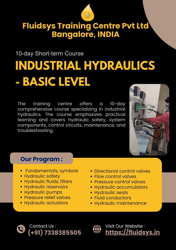
Fluidsys Training Centre Pvt. Ltd., Bangalore
Fluidsys Training Centre Pvt. Ltd., Bangalore, India
Mob: +917338385505
email: info@fluidsys.org | Website: https://fluidsys.org
Book
A complete range of 36 textbooks, in Paperback & Kindle eBooks Editions, on Pneumatics and Hydraulics, under the Fluid Power Educational Series, authored by Joji Parambath, has been released. For more details, please visit:
Course


")


")

Great informative article with easy to understand words and sentences good work. Can you please tell me difference between close loop and open loop circuit please don’t be confused it’s circuit
LikeLike