
In the electrical actuation of a hydraulic valve, the necessary actuating force is obtained electrically with the help of a solenoid. The off-centre core of the solenoid coil is pulled towards the centre of the coil when the electric current is passed through it. This discrete movement of the core is used to actuate the solenoid valve. The solenoid valve in an electro-hydraulic system acts as an interface between the hydraulic part and the electrical part of the system.
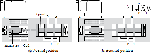
4/2-way Single-solenoid Valve, Spring Return
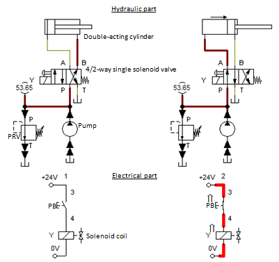
In the normal position of the solenoid valve, the pressure port P is connected to the working port B, and the working port A is connected to the tank port T. The valve is actuated when the rated voltage is applied to the coil Y. In the actuated position of the valve, the port P is connected to the port A, and the port B is connected to the port T. When supply to the coil is cut off, the valve returns to its normal position. This valve can be used as the final control element for controlling a double-acting cylinder.
4/2-way double-solenoid Valve
A 4/2-way double-solenoid electro-hydraulic valve consists of two solenoid coils on either side of the valve controlling its hydraulic part. The valve remains in a particular position due to applying a pulse or continuous signal to the coil at one end as long as no opposing signal is presented to the coil at the other end. Hence, this valve shows the memory characteristics.
Control Devices
Many control elements, such as pushbuttons, relays, timers, and sensors, are used in electro-hydraulic systems to realise various control functions.
Push-button Switch
A push-button switch is used to close or open an electric circuit. This control device comprises a push-button actuating head, fixed and movable contacts, and a restraining spring. Pressing the push-button against the restraining spring operates its contacts.
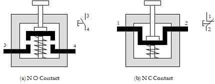
The types of contacts distinguished according to their functions are (1) Normally open (NO) type, (2) Normally closed (NC) type, and (3) Change-over (CO) type.
Terminal Markings of Contacts
For identification purposes, the terminals of each of the contacts of the control device are designated with a set of numbers based on the contact function and the control device type.
| Control element types | Terminal designations for: | Terminal designations for: |
| NC contact | NO contact | |
| Ordinary devices (PBs, relays) | 1 and 2 | 3 and 4 |
| Special relays (Timers, counters) | 5 and 6 | 7 and 8 |
In the electrical actuation of a hydraulic valve, the necessary actuating force is obtained electrically with the help of a solenoid. The off-centre core of the solenoid coil is pulled towards the centre of the coil when the electric current is passed through it. This discrete movement of the core is used to actuate the solenoid valve. The solenoid valve in an electro-hydraulic system acts as an interface between the system’s hydraulic and electrical parts.
Superlative Textbook on
Electro-hydraulic Systems and Relay Circuits
by Joji Parambath
This book explains the functioning of primary solenoid valves and various electrical control components. Many typical single-actuator electro-hydraulic circuits are developed to illustrate various applications of electro-hydraulics.
Click on the image or book title to go to the Amazon site
4/2-way Single-solenoid Valve, Spring Return
In the normal position of the solenoid valve, the pressure port P is connected to the working port B, and the working port A is connected to the tank port T. The valve is actuated when the rated voltage is applied to the coil Y. In the actuated position of the valve, the port P is connected to the port A, and the port B is connected to the port T. When supply to the coil is cut off, the valve returns to its normal position. This valve can be used as the final control element for controlling a double-acting cylinder.
4/2-way double-solenoid Valve
A 4/2-way double-solenoid electro-hydraulic valve consists of two solenoid coils on either side of the valve controlling its hydraulic part. The valve remains in a particular position due to the application of a pulse or continuous signal to the coil at one end as long as no opposing signal is presented to the coil at the other end. Hence, this valve shows the memory characteristics.
Control Devices
A number of control elements such as pushbuttons, relays, timers, and sensors are used in electro-hydraulic systems to realise various control functions.
Push-button Switch
A push-button switch is used to close or open an electric circuit. This control device consists of a push-button actuating head, fixed and movable contacts, and a restraining spring. Pressing the push-button against the restraining spring operates its contacts.
The types of contacts distinguished according to their functions are (1) Normally open (NO) type, (2) Normally closed (NC) type, and (3) Change-over (CO) type.
Terminal Markings of Contacts
For identification purposes, the terminals of each of the contacts of the control device are designated with a set of numbers based on the contact function and the control device type.
| Control element types | Terminal designations for: | Terminal designations for: |
| | NC contact | NO contact |
| Ordinary devices (PBs, relays) | 1 and 2 | 3 and 4 |
| Special relays (Timers, counters) | 5 and 6 | 7 and 8 |
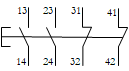
Pushbutton Station
A push-button station comprises many contact sets (NO, NC or CO) with a common actuation. A pair of successive two-digit numbers is used to designate the terminals of a contact in the pushbutton station. In the two-digit number, the digits in the unit place indicate the function of the contact (that is, whether it is an NO type or an NC type), and the digits in the ten’s place merely represent a serial ordering of all contact sets in the pushbutton station for identifying each contact set uniquely.
Direct control of a double-acting hydraulic cylinder
Two positions of a self-explanatory electro-hydraulic circuit for the direct control of a double-acting cylinder are given below. You may take a serious look at the circuit for a proper understanding of the electro-hydraulic system.
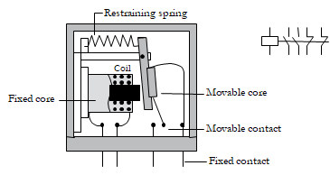
Electromagnetic Relay
The relay mainly consists of a coil and many independent contact sets. Each contact set consists of a stationary contact and a movable contact. It also includes stationary and movable cores to confine the magnetic field. The movable contacts are coupled to the movable core. Therefore, when the coil is energized with the help of an additional electrical circuit, the movable core is pulled towards the stationary core, thus simultaneously operating all its coupled contacts. This movement either makes or breaks the connection of the movable contact with its respective fixed contact in each contact set.
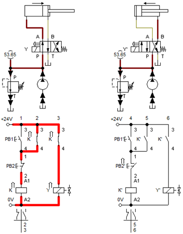
Indirect control of a double-acting hydraulic cylinder using a relay
Two positions of a self-explanatory electro-hydraulic circuit for the indirect control of a double-acting hydraulic cylinder are given below.

Logic Controls, Electric
Logic controls are used to start or stop various hydraulic systems operations based on the satisfaction of certain conditions. Two of the most important logic functions are ‘AND’ and ‘OR’. These functions logically combine signals representing certain conditions in a system. The AND logic function produces the output when all the inputs are present. The output is produced in the OR logic function when one or more (≥1) inputs are present.
Memory Function
A circuit/device with a memory function ‘remembers’ its last output state even after removing the input signal from an input device responsible for this output. A memory function can be implemented in electro-hydraulic circuits using an electrical latching circuit or a double solenoid valve.
Latching Circuit, Electric
The electrical latching circuit is given in its latched and unlatched positions.
Sensors
Sensors can detect the presence of objects. A sensor can work either by the actual physical contact with an object or by the object’s movement in its proximity. Accordingly, the sensors are classified as contact-type sensors (e.g. limit switch) and contactless-type sensors (e.g. proximity sensors).
Limit Switch
A limit switch is a contact-type sensor comprising switching contacts (NO/NC/CO type), a roller-operated plunger, and return springs. The roller lever is mechanically linked to the contacts. It is usually actuated mechanically by a moving element, such as a cylinder piston, in the associated machine to indicate a particular position of the moving element.

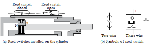
Reed Switch
A reed switch consists of two metal strips (reeds) acting as switching contacts. It is hermetically sealed in a glass tube filled with an inert gas to prevent the corrosion of its contacts. This unit is further encapsulated in an epoxy resin casing. It is designed to be mounted on a cylinder. It reacts to the magnetic fields of the permanent magnets on the cylinder piston.
Proximity Sensors
A proximity sensor is a contactless-type sensor that detects the presence of an object using a detection system and converts this information into a corresponding electrical signal. One detection system uses the eddy currents generated in a metallic sensing object by interacting with the detection system and the object. Another type detects the changes in the electrical capacity of the capacitor in the detection system when an object approaches the sensor. Yet another type detects objects through a variety of optical properties. Accordingly, there are three basic types of proximity sensors. They are (1) Inductive-type sensors, (2) Capacitive-type sensors, and (3) Optical-type sensors.
Inductive Proximity Sensor
Inductive proximity sensors are widely used in modern high-speed industrial and process control systems to detect metallic objects. An inductive proximity sensor consists of the following blocks (1) an oscillator circuit, (2) a switching circuit, (3) an amplifier, and (4) an output stage, all housed in a resin-encapsulated body.
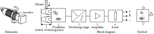
A part of the oscillator circuit is a coil capable of producing high-frequency magnetic oscillations in the active switching area when the rated voltage is applied to the sensor. If any metallic object is brought near to the active switching area of the sensor, eddy currents are generated in the object. The eddy currents are converted into heat. In fact, this loss draws energy from the oscillator. As a result, the oscillations are weakened. The switching circuit converts this oscillator state into a clear signal through the switching stage. Finally, the output signal is amplified and delivered to the load circuit. The sensing range of inductive proximity sensors is usually small, typically up to 12 mm.
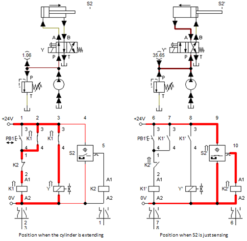
Semi-automatic operation of a double-acting hydraulic cylinder using a sensor
The hydraulic part and the electrical part of the circuit for the semi-automatic operation of a double-acting hydraulic cylinder using a proximity sensor (S2) are given in the Figure below, which is self-explanatory.
Time-delay Relays (Timers)
A time-delay relay (or timer) is a control device used to obtain a specified time delay between the work operations in an industrial system. There are two basic types of timers. They are (1) On-delay timer and (2) Off-delay timer.
On-delay Timer: An on-delay timer delays the operation of its contacts for, say, ‘t’ seconds when the coil is energized (ON), but the timer brings back its contacts immediately to their normal positions when the coil is de-energized (OFF).
Control of a double-acting cylinder using a timer
You may test your understanding of electro-hydraulics by analyzing the two critical positions of a self-explanatory electro-hydraulic circuit with an on-delay timer, as given below.

Authored by JOJI Parambath, Founder/Director, Fluidsys Training Centre, Bangalore
A complete range of 32 textbooks, in Paperback & Kindle eBooks Editions, on Pneumatics and Hydraulics, under the Fluid Power Educational Series, authored by Joji Parambath is released. These books under the fluid power educational series are written to spread the knowledge of pneumatics and hydraulics. The language of these books is simple, the topics in each book are logically arranged, and information is most up-to-date.
Please visit jojibooks for more details.
Fluidsys Training Centre Pvt. Ltd., Bangalore, India
Mob: +917338385505
email: info@fluidsys.org | Website: https://fluidsys.org


")
")


Leave a comment