The basic concepts of a relay control system and a PLC control system are highlighted in this article with the help of a circuit diagram. Assume that an electro-pneumatic system is used to obtain an industrial work operation. The system consists of a pneumatic power part and an electrical control part. The electrical control part may be a direct control system, a relay control system, or a PLC control system. Let us have some details…

The Pneumatic Power System
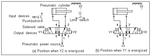
Figure 1: Pneumatic part of an electro-pneumatic system
The pneumatic power part consists of a power source, a double-acting cylinder, and a double-solenoid directional control valve. The power source generates and delivers compressed air to the pneumatic system. The cylinder converts the pneumatic power to linear mechanical power. The directional control valve is actuated by solenoid coils Y1 and Y2 and controls the air flow direction to the actuator. Two positions of the pneumatic power part are shown. Figure (a) shows the position when the solenoid Y2 is energized, and figure (b) shows the position when the solenoid Y1 is energized. Please observe the flow paths of compressed air directed to the cylinder and the corresponding direction of motion of the cylinder. When the solenoid Y2 is energized, the cylinder retracts, and when the solenoid Y1 is energized, the cylinder extends. The pneumatic power part is controlled by the electrical control part.
The Electrical Control System
The electrical control part consists of a pushbutton (PB1), a limit switch (or sensor) (S1), and solenoids (Y1 and Y2). The sensor is used to get automatic operation. The pushbutton and sensor are input devices. The solenoids are output devices. The typical industrial control voltage is 24 V DC in most parts of the world. Remember, other voltage types and levels can also be used. The input devices generate control signals and energize the output devices. According to the way the output devices are controlled by the input devices, the control system may be classified as (1) a Direct control system, (2) a Relay-based control system, and (3) a PLC-based control system.
Direct Control System

Figure 2: Direct control system
In the direct control system, the input devices directly control the output devices. For example, as shown in the figure, the pushbutton PB1 directly controls the solenoid Y1 (See circuit 1) to obtain the forward motion of the cylinder. The sensor S2 directly controls the solenoid Y2 (See circuit 2) to obtain the automatic return motion of the cylinder. Direct control systems are rarely used in applications, as the lowly-rated input devices may be incapable of switching the current drawn by the output devices. A complex system needs a controller, like a relay controller or a PLC controller, to take care of the current switching requirements of the control system.
Relay-based Control System
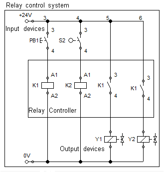
Figure 3: Relay-based control system
Relays interface the input devices with the output devices in a relay-based control system. A relay consists of a coil and switching contacts. The relay contacts are operated when the relay coil is energized (24 V DC). The function of a relay is as simple as that mentioned here. The figure shows that the pushbutton PB1 controls the solenoid Y1 through the relay K1. The pushbutton PB1 is connected to the relay coil K1 (See Circuit 3), and the solenoid Y1 is switched through the relay contact K1 (See Circuit 5). Similarly, the sensor S2 controls the solenoid Y2 through the relay K2. The sensor S2 is connected to the relay coil K2 (See Circuit 4), and the solenoid Y2 is switched through the relay contact K2 (See Circuit 6). Overall, the inputs PB1 and S2 control the outputs Y1 and Y2 through the relays K1 and K2. The boxed section with relay coils and contacts constitutes the relay controller. More complex logic functions, timing functions, counting functions, etc, can be hard-wired into the relay-based control systems.
PLC-based Control System
A PLC-based control system attempts to replace the relay controller. Instead, it uses an electronic controller and a software program to interface the inputs of the controlled system with the outputs. That is, a PLC consists of hardware and software.
A simple PLC hardware mainly consists of a CPU, memory, input, and output modules. Input and output modules can be called I/O modules. The CPU executes the software program. The software part and the status of the input and output signals are stored in the memory. The input modules are classified into digital input modules and analog input modules. The output modules are classified as digital output modules and analog output modules. A digital input module prepares the 24 V DC digital input signals to be appropriate for the CPU’s voltage level (Typically 5 V DC). An analog input module converts the analog input signals into equivalent digital values. A digital output module converts the digital output signals from the CPU to be appropriate for the output devices. An analog output module converts digital values into equivalent analog output signals appropriate for driving the analog output devices. Many inputs and outputs can be provided for a PLC.
The software part of the PLC consists of the operating system with programming languages and user programs. The operating system essentially controls the hardware optimally. The programming language includes instructions to scan the inputs and energize the outputs. It also includes timing and counting instructions. A PC loaded with the operating software can be used to write user programs that can be downloaded to the PLC.
I/O Connection: As shown in the figure, the input devices are connected to the addressed input module. That is, the pushbutton PB1 is connected to the input of the PLC at address I2 and the sensor S2 is connected to the input at the address I7. The solenoid Y1 is connected to the output of the PLC at address Q3, and the solenoid Y2 is connected to the output at address Q8.
Ladder Programming: The ladder programming language is the most popular and can be used to program the PLC. The ladder programming language consists of instructions in a graphical form and can be arranged in the form of a ladder, similar to an electrical control circuit. The left line of the ladder represents the power line, and the right line represents 0 V.

Figure 4: PLC-based control system
A program ‘NO contact’ with the specified address can be used to scan the’ on’ condition of an addressed input. A program ‘coil’ with the specified address can be used to energise the addressed solenoid. For example, in the first rung of the ladder program, as shown in the figure, a program NO contact with the input address I2 (where the pushbutton PB1 is linked) is connected to a program coil with the output address Q3 (where the solenoid Y1 is linked). When the pushbutton PB1 is pressed, the address I2 turns to the ‘1’ state, allowing hypothetical energy to flow to the coil. The output address Q3 now turns to the ‘1’ state and energizes the output solenoid Y1. When the solenoid Y1 is energized, the valve is actuated, and the cylinder extends.
Similarly, in the second rung of the ladder program, as shown in the figure, a program NO contact with the input address I7 (where the sensor S2 is linked) is connected to a program coil with the output address Q8 (where the solenoid Y2 is linked). When the sensor S2 is actuated, the address I7 turns to the ‘1’ state, allowing hypothetical energy to flow to the coil. The output address Q8 now turns to the ‘1’ state and energizes the output solenoid Y2. When the solenoid Y2 is energized, the valve is actuated, and the cylinder retracts.
In the PLC-based control system, the outputs are controlled by the governing program and the condition of the inputs. That means the control changes when the software program changes.
Application of Relay Controllers and PLCs
A relay controller is economical and is usually used where the control requirements remain fixed. A PLC controller is used where the control program changes frequently.
By
Joji Parambath
Fluidsys Training Centre Pvt. Ltd.
Bangalore, India
The details of the course calendar, course contents, course fee, etc. can be obtained by contacting us or visiting our website.
Fluidsys Training Centre Pvt. Ltd., Bangalore, India
Mob: +917338385505
email: info@fluidsys.org | Website: https://fluidsys.org

For more information, please read our publication, Electro-Pneumatics and Automation.
Fluidsys Training Centre, Bangalore, offers long-term and short-term training courses in pneumatics and hydraulics.
Long-term course
Pneumatics & Hydraulics – Advanced Level
The 12-week long-term course, namely Pneumatics & Hydraulics – Advanced Level, is meant for Graduates and Diploma holders in Mechanical / Electrical / Electronics / Computer science who can attend the course to become complete fluid power professionals.
Brief Course Content (Pneumatics & Hydraulics – Advanced Level):
Pneumatics: Safety practices, Industrial prime movers, Compressed air generation and treatment, Pneumatic actuators, Valves and control circuits, Electro-pneumatics, Multiple-actuator pneumatic and electro-pneumatic circuits, Pneumatic applications, Design, and Maintenance and troubleshooting of pneumatic systems.
Hydraulics: Hydraulic safety, Hydraulic fundamentals, Fluids, Filters, Power packs, Pumps, Pressure relief valves, Linear actuators, Rotary actuators, Hydrostatic transmission (HST), Directional control valves, Non-return valves, Flow control valves, Pressure Control Valves, Accumulators, Seals, Fluid conductor system, Electro-hydraulics, Proportional valve system, Servo valve system, Basics of hydraulic cartridge valve systems, Load Sensing Systems, Applications of hydraulic systems, Preventive maintenance & troubleshooting, and Design of hydraulic systems.
Programmable Logic Controllers (PLCs)
Employability Skills: Stress Management, Decision Making & Problem-Solving, Team Building, Interpersonal Skills, Leadership, Time Management, Communication Skills, and Emotional Intelligence.
Short-term Courses:
- Industrial Hydraulics – Basic Level (5 days)
- Design of industrial hydraulic systems (4 days)
- Electro-hydraulic systems and circuits (4 days)
- Pneumatic controls –Basic level (4 days)
- Eletro-pneumatics and automation (4 days)
Need-based Courses:
Apart from the scheduled courses, the centre conducts tailor-made and need-based training courses in Pneumatics and Hydraulics.


")


")


Leave a comment