
The article looks at the basics of pressure control valves for educational use and is presented here to refresh your memory. Hope you can recall the functions, circuits, and applications of pressure control valves.
Pressure control valves are used in hydraulic systems to obtain pressure-related control functions. Pressure control valves can be categorized into: (1) pressure-reducing valves, (2) unloading valves, (3) sequence valves, (4) counterbalance valves, and (5) brake valves.

Industrial Hydraulic Systems and Circuits Basic Level in the SI Units
By Joji Parambath
The textbook deals with the components and circuits of hydraulic systems. It initially provides the fundamentals required to understand the core topics. The book then describes in detail the topics of power packs, hydraulic actuators, and directional, flow, and pressure control valves. Next, it also presents the maintenance, troubleshooting, and safety aspects of hydraulic systems. The book uses the English system of units.
Industrial Hydraulics Basic Level in the English Units
By Joji Parambath
Please click on the image to go to the Amazon Website book links
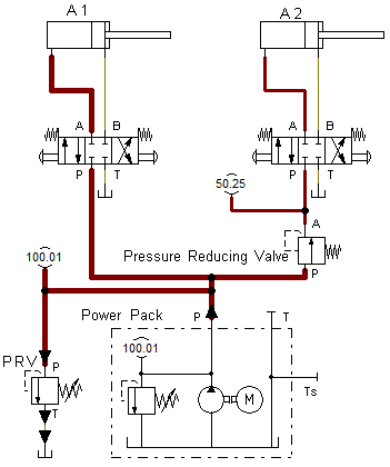
Pressure Reducing Valve
The primary role of the pressure-reducing valve in a hydraulic system is to limit the pressure in some parts of the system to a value lower than that required for the rest of the system. The reduced pressure can be set by using a control spring. The valve consists of an inlet port ‘A’, an outlet port ‘B’, a spring-loaded spool, and a pressure-adjusting screw. The valve is provided with an internal control passage to evaluate the outlet pressure (at port B). When the outlet pressure remains below the valve setting, the fluid flows freely from the inlet to the outlet (that is, from A to B). When the pressure at the outlet exceeds the valve setting, the spool shifts to block the outlet port, thus maintaining a reduced pressure in the regulated line.

For example, an excess force (pressure) applied to the clamping operation by cylinder A2 may damage the clamped workpiece. In such a situation, a pressure-reducing valve can limit clamping pressure only. You may observe the pressure values in parts of the circuit below.
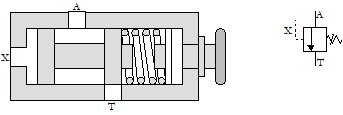
Unloading Valve
An unloading valve consists of an inlet port ‘A’, a tank port ‘T’, a pilot port ‘X’, and a spring-biased spool. The unloading pressure can be varied by adjusting the spring tension. The pilot port is provided to accept the external pressure signal, which acts on one end of the spring-biased valve spool. In the normal position, the valve remains closed by the spring force. When a sufficient signal is applied to the pilot spool, the spool shifts, and the pump delivery is diverted to the reservoir through the tank port (that is, from A to T) at low pressure. The primary function of the unloading valve is to regulate the pressure by bypassing the fluid to the system reservoir at a low energy level in response to the external pressure signal received from the load section of the system. Unloading valves can be used in accumulators, hydraulic motors, and two-pump ‘hi-lo’ circuits.
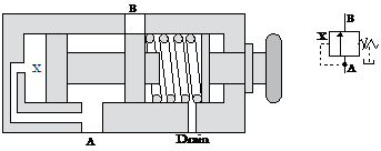
Sequence Valve
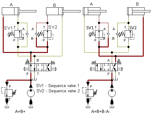
A sequence valve consists of an inlet port ‘A’ an outlet port ‘B’, a spool and a spring. The valve remains closed by the spring force. The externally adjustable spring is provided to set the pressure to the required value. A pilot passage ‘x’ is provided in the valve to accept signals from the inlet to act on one side of the spool. When sufficient pilot pressure is applied, the spool moves against the spring force and opens the valve, thus allowing the flow through the valve. The valve is kept open until the pilot’s sensing pressure exceeds the spring bias. They are available with built-in check valves, each permitting an unrestricted reverse flow. The spring chamber in the sequence valve is drained externally to the system reservoir to negate the effects of back pressure.
Pressure sequence valves can be used to obtain sequential operations of work processes. For example, they can be used in a hydraulic system with a clamping cylinder ‘A’ and a drilling cylinder ‘B’ to get the sequence control of these cylinders. The two critical positions of the circuit are shown in the figure below. The first part of the circuit shows the condition when the 4/3-way valve is shifted to its left-hand side envelope. When cylinder A reaches the end of its forward stroke to clamp a workpiece, the pump pressure at the inlet of the sequence valve SV2 increases and hence, the sequence valve (SV2) opens, allowing the drilling cylinder B to move forward to control the movement of the drill unit. The second part of the circuit shows the condition when the 4/3-way valve is shifted to its right-hand side envelope. When cylinder B reaches the end of its return stroke, the pump pressure at the inlet of the sequence valve SV1 increases and hence, the sequence valve (SV1) opens, allowing cylinder A to return to its home position.
Counterbalance Valve
The counterbalance valve is normally closed with inlet ports ‘A’ and an outlet port ‘B’. It also consists of a spring-loaded spool. The externally adjustable spring is provided to set the pressure. The counterbalance must be set at a little higher pressure than required to retain the load. A pilot passage is provided to accept a signal from the load side of the valve, and the signal acts on one side of the spool. The flow path through the valve opens when the pressure at the pilot port increases beyond the pressure setting. When open, the valve discharges the fluid from the inlet port to the outlet port. The valve closes when the pressure drops below the setting of the spring. The main function of the counterbalance valve in a hydraulic circuit with a load-carrying actuator is to maintain the preset backpressure in the return line of the circuit, sufficient to balance the load held by the actuator.

Vertically mounted cylinders connected with heavy loads or hydraulic motors on winch drives are susceptible to the dangers associated with overrunning loads.
Joji Parambath
Director
Fluidsys Training Centre Pvt Ltd
Bangalore, India

")


")


Leave a comment