
Hydraulic systems driven by servo valves provide highly accurate control over enormous forces. A servo valve system consists of a transducer, a servo amplifier, a servo valve, and an actuator with a connected load. It is a closed-loop system used to precisely control the output (load) parameter, such as position, velocity, or force, in response to a command signal. The transducer converts the output into an equivalent electrical signal. This feedback signal is compared to a command signal (representing the required output) to generate an error signal. The amplifier amplifies the error signal.
The amplified signal controls the valve. The servo valve regulates the fluid flow in proportion to the current from the amplifier. The actuator then drives the load to move precisely to reduce the error signal. According to the type of feedback signals, closed-loop servo systems can be classified into three basic types: (1) Position servo system (2) Velocity servo system and (3) Pressure/Force servo system.
Servo Amplifier

It mainly contains a summing junction, an amplifier with a PID circuit, a ramp generator, and a dither oscillator. The servo amplifier generates an error signal due to the difference between the measured output signal and the command input signal at the summing junction.
The servo valve responds to the amplifier signal by controlling fluid delivery into/out of the actuator. A PID circuit in the amplifier controls how the system approaches the desired output. The ramp generator controls the rate of change of the amplifier’s output and consequently controls the rate at which the valve opens or closes. The dither oscillator can be used in the amplifier to reduce the effects of friction due to the sliding of the spool against the valve body and inertia.
Servo Valves
A servo valve is a precisely machined spool-type directional control valve with a current-driven mechanism using a torque motor to control the spool position. A torque motor can be considered an electromechanical transducer that produces a small deflection proportional to the input current. It can impart the necessary motion to the spool either directly or indirectly. The spool can be infinitely positioned to control the flow direction and the amount of pressure in response to electrical/ electronic control signals.
Servo valves are available in one-stage, two-stage, or three-stage designs. A single-stage servo valve consists of a torque motor directly attached to the sliding spool of the valve. The torque motor must supply enough torque to the valve to shift its spool directly against an opposing pressure. The single-stage valve has limited power capability. A two-stage servo valve consists of a torque motor, a pilot spool, and the main spool. First, the torque motor shifts the pilot spool, which, in turn, directs fluid flow to move the main spool. In a three-stage servo valve, the pilot stage is divided into two, namely, 1st stage pilot and 2nd stage pilot. The first-stage pilot spool shifts the second-stage pilot spool, which, in turn, shifts the main spool. The three-stage servo valves are used for applications with high-flow, high-pressure requirements.
Torque Motor
A torque motor consists of upper and lower pole pieces, an armature, two coils, a flapper and a flexure tube. The two pole pieces – one polarized ‘North’ and the other polarized ‘South’ – provide paths for the magnetic flux. The armature is mounted on a pivot and suspended in the magnetic field’s air gaps. Its ends are positioned in the middle of the air gap between the upper and lower pole pieces.
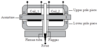
When electric current flows through these coils, the armature gets polarized. One end of the armature is attracted to one pole piece, and the other end is repelled by the same pole piece at the other end. This way, depending on the magnetic polarity, the torque motor converts the input signal to a proportionate semi-rotary movement of the armature, either clockwise or anti-clockwise. The displacement of the armature is limited to a few thousandths of an inch.
The small deflection of the armature can be used to control the pilot stage of the servo valve through the connecting mechanism. Two main forms of construction are used to connect the armature to the pilot stage of the valve. They are: (1) the flapper nozzle arrangement and (2) the jet pipe arrangement. The flapper-nozzle arrangement is explained below.
Flapper Nozzle Arrangement
It consists of a flapper lever and two nozzles. The armature/flapper assembly is supported on a flexure tube that allows it to rotate until the torque produced equals the restraining torque in the flexure tube. A flapper lever, attached to the armature of the torque motor, is aligned between the two nozzles. This arrangement forms two variable orifices between the nozzle tips and the flapper.

The movement of the flapper lever controls the flow through the nozzles. If the torque motor rotates the flapper counter-clockwise, the orifice on the right-hand side becomes smaller than on the left-hand side. The resulting pressure on the right-hand side of the spool becomes greater than that on its left-hand side. This pressure difference moves the spool to the left by an amount proportional to the current level in the armature coil. The position of the spool controls the amount, rate, and flow duration. As the spool moves in response to the pressure differential across the spool, a feedback wire exerts an opposite torque on the armature/flapper assembly, trying to re-centre the flapper. The spool continues to move until the torque produced by the feedback wire equals that produced by the control signal. This armature/flapper assembly arrangement imparts a controlled motion to the spool and positions the spool in proportion to the input current.
Lap Conditions in Servo Valves
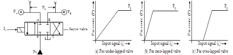
Three critical lap conditions exist in servo valves according to the width of the spool land in comparison with the width of the opening of the associated port in the sleeve: (1) Line-to-line (zero-overlap), (2) Open-centre (under-lapped), (3) Closed-centre (over-lapped).

- Zero-overlap: In the zero-overlap (line-to-line) configuration, the valve spool is machined and aligned precisely to obtain a line-to-line fit of the flow-metering edges with the opening in the valve body. Therefore, the zero-lapped valve can deliver a flow to the connected actuator ports immediately in response to a differentially small spool shift, either way.
- Under-lapped: In an under-lapped (open-centre) servo valve, the land width of the spool is smaller than the port width of the valve. Therefore, the under-lapped valve delivers a flow even when the valve remains in its centre.
- Over-lapped: In an over-lapped (closed-centre) servo valve, the spool land width exceeds the port width. The over-lapped valve has a ‘deadband.’ This means the spool must move a certain distance before a flow can be delivered.
Null Drift and Null Adjustment
There is a tendency for a servo valve, especially the zero-lapped one, to drift from its centre position due to the presence of contamination or variations in temperature, supply pressure, or load pressure. A shift in the null position of the valve is indicated when the associated actuator experiences significant flow at zero input signal and causes errors in the system. It is often necessary to readjust the null position by turning the null screw to make the flow output to zero or make the pressures at the blocked working ports of the valve equal when no input signal is applied.
Servo Valve Characteristics
A system response has two essential components: (1) Transient (dynamic) response and (2) Steady-state response. The transient response represents the momentary variations of the system parameters, such as pressure and flow rate, in response to a sudden change in the input signal applied to the system. If the system is inherently stable, the transient response disappears soon. The steady-state condition is a state in which system parameters, such as flow rate and pressure, do not vary significantly with time after the initial fluctuations of the parameters have disappeared.
Steady State Characteristics
Two types of gains are usually set for servo valves. Flow gain and pressure gain are the two essential steady-state parameters. Other parameters are the pressure drop across the valve, hysteresis, threshold (resolution), linearity, and symmetry.
Flow characteristics

Pressure Characteristics
Transient (Dynamic) Characteristics
The transient response can be described by its ‘step response’ and ‘frequency response’.
Step Response
It is measured by recording the spool displacement (x) versus time for a step input current (I). Usually, there are two possibilities when a step input is applied to the servo valve under no-load conditions. The system may appear as what is known as a first-order system or a second-order system.

First-Order System
The behaviour of a first-order system to a step input is given below. The Time constant of a first-order servo valve is the time required for its output to reach about 63% of the steady-state value. The settling time is required for its output to reach and stay within a defined tolerance band.

Second-Order System
In the second-order system, the output increases rapidly, overshoots the steady-state condition, and eventually settles at an appropriate value in response to a step input function. The most important parameters are defined below:

- Delay Time: The time required for the output to reach 50% of its steady-state value.
- Rise Time: The time required for the output to rise from 10%-90% of its steady-state value.
- Maximum Overshoot Time: The time at which the maximum overshoot of the output occurs.
- Settling Time: The time for the output to reach and stay within its stated tolerance band.
Sinusoidal Input (Frequency) Response
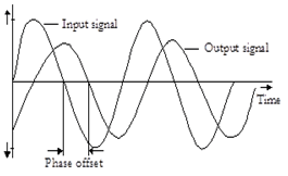
A step response is not considered an exceptional measure of the valve’s performance because of the inherent inaccuracies in measuring it. A much more accepted method of measuring the transient response is subjecting the valve to a sinusoidal input signal over a range of frequencies and then comparing the behaviour of the output flow of the valve for each frequency. When a sinusoidal input signal is applied to the valve, its output follows the input signal with some error. At low frequencies, the output follows the input signal. At high frequencies, the error tends to increase.
The frequency response is usually measured with constant input current amplitude and a zero pressure drop across the load. It is measured with the two parameters: (1) Amplitude ratio and (2) Phase angle (Shift).
Amplitude Ratio (AR)
It is the ratio of the flow amplitude at any frequency to that at a specified reference frequency (typically 5 Hz). The amplitude ratio is usually expressed in decibels (dB).
Amplitude ratio = 20 log10 (AR) dB
Phase Angle (lag)
It is the degree difference between the phase of a sinusoidal input current and the corresponding phase of the output flow, measured at a specified frequency.
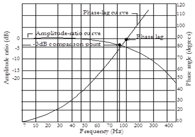
The figure shows the typical dynamic response of a second-order system with an Amplitude-Ratio curve and the phase-lag curve over some frequency range. The dynamic response of the valve can easily be determined by referring to the frequencies at which –3 dB amplitude ratio (AR) and 90° phase angle occur.
Electro-hydraulic Servo Positioning System
The basic objective of the position servo system is to move the hydraulic actuator to the desired position and stop. This objective requires a closed-loop control system that has a command signal and a feedback signal. Once the actuator is in the desired position, the two signals produce a zero error signal (position error) in the system. Then, the servo valve must close to hold the actuator in place.

Effect of Contamination on Servo Valves
Servo valve clearances are tiny, and, therefore, they are extremely prone to fluid contamination. Contamination can gum up the valve and result in its reduced response.
Application of Servo Valves
Electro-hydraulic servo valves are used in high-precision systems employing high-power hydraulics controlled by low-power (< 200 mW) electronics. Closed-loop electro-hydraulic servo systems are increasingly becoming the norm in machine automation, where the system requirements demand greater precision. Servo valves find applications in a process plant, power generation, and mining. The plastic manufacturing sector uses the power and precision of servo valves to improve the quality of blow-moulded and injection-moulded parts. The steel industry is a unique branch where the power of hydraulics is essential, along with the precision of electronic control. Servo valves are also gaining wide acceptance in various application areas, such as material handling, oil and gas, and mobile equipment.
Authored by JOJI Parambath, Founder/Director, Fluidsys Training Centre, Bangalore
Email: info@fluidsys.in | website: https://fluidsys.org
Reference: Electro-hydraulic Servo Valves by Joji Parambath
Please contact Fluidsys Training Centre Pvt. Ltd., Bangalore, for training in Pneumatics, Electro-pneumatics, Hydraulics, Electro-hydraulics, etc.
Electro-hydraulic Servo Valves
Joji Parambath


")


")


Leave a comment