Most practical pneumatic systems involve multiple actuators (cylinders, semi-rotary actuators, etc.), which carry out the desired control tasks when operating in specified sequences. Double-pilot directional control (DC) valves are used as final control elements to control the forward and return strokes of the actuators. Sensors are used to confirm the actuator positions and provide signals to the final control elements. However, it is important to remember that the double-pilot DC valves are susceptible to the problem of ‘signal conflicts’. You may remember that the signal conflict is due to the appearance of pilot signals simultaneously on both sides of a double-pilot DC valve, which will cause the valve to be unable to move its position in response to a control signal.
A complete range of 36 books, in Paperback & Kindle eBooks Editions, on Pneumatics and Hydraulics, under the Fluid Power Educational Series, authored by Joji Parambath, has been released. For more details and for the latest blogs, please visit:
Control Task
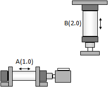
A pneumatic circuit has to be developed for realizing the following control task using two cylinders A (1.0) and B (2.0) as shown in the schematic diagram. The cylinder A is to extend and bring a job under the stamping cylinder B. Cylinder B is then used to extend and stamp the job. Cylinder A can return only after cylinder B has retracted fully. The sequential control task can also be expressed in a displacement-step diagram.
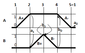
Displacement-step Diagram
The displacement-step diagram for the control task is given below. The displacements of cylinders are plotted in equal steps following the required sequence of the cylinder actions. For example, the displacement of any cylinder from the retracted position (0) to the extended position (1) is shown in the diagram with a line from 0 to 1. Similarly, other displacements can also be shown.
Notational Form of the Control Task
In the notational form, the ‘+’ sign is appended to the cylinder designation (A, B, etc) to represent the forward stroke and the ‘-’ sign is appended to it to represent the return stroke. For the control task specified above, the sequence of the cylinder actions, along with the details of the sensor outputs, can be represented by:
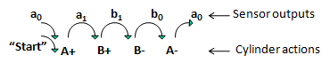
As can be seen, the A+ action generates ‘a1’ signal and is used for the B+ action, the B+ action generates ‘b1’ signal and is used for the B- action, and so on. Usually, a “Start” signal is also required along with the a0 signal (the last signal of the control sequence) to obtain the A+ action (the first cylinder action of the control sequence).
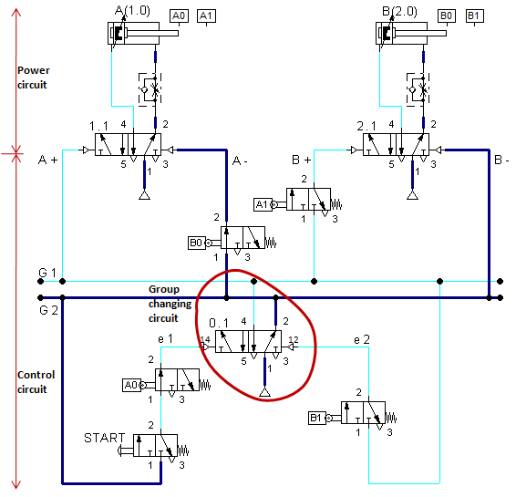
Adding the Control Circuit to the Power Circuit
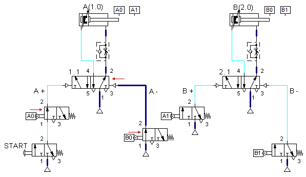
As shown in the figure, incorporate all the sensors and the “Start” pushbutton as per the required control sequence. Represent the sensors a0 and b0 initially in the actuated state.
Check for Signal Conflict
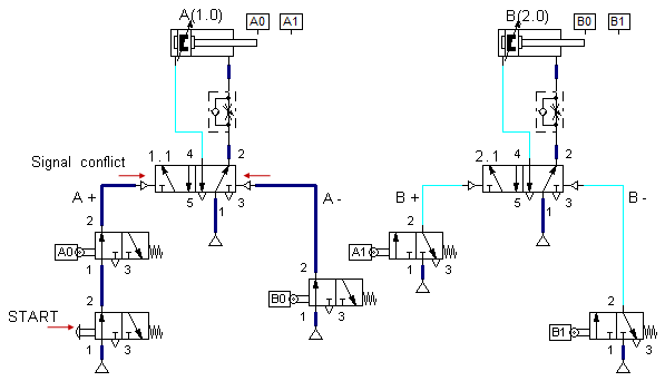
The next step is to analyze the circuit for signal conflicts. When the “Start” pushbutton is pressed, a signal appears at port 14 of valve 1.1 through sensor a0. It can be seen that a signal is also present at port 12 of valve 1.1, resulting in a signal conflict. As a result, valve 1.1 cannot switch over, and the circuit will not work. You may check for other signal conflicts, if any.
Elimination of signal conflicts
Various methods are devised to eliminate the problem of signal conflicts. Most popular methods are based on controlling the air supply to different control circuit sections. The following methods may be used to avoid the signal conflicts: (1) Cascade method and (2) Shift register. This article explains only the cascade method of eliminating the signal conflict.
Cascade method
In this method, the sequence of operations of cylinders, that is, A+B+B-A- are divided into appropriate groups so there is no possibility of a signal conflict. In case A+ and A- happen to be in the same group, signals can appear simultaneously at both ends of the final control element (valve 1.1) controlling cylinder A. Similarly, signals can appear simultaneously at both ends of the final control element (valve 2.1) controlling cylinder B if the cylinder actions B+ and B- happen to be in the same group. Hence, the sequence of operations is divided so that the A+ and A- actions fall into different groups (G1 and G2), and the B+ and B- actions fall into different groups (G1 and G2), as demonstrated.

It should be remembered that the desired sequence should be maintained. In this method, every attempt should be made to keep the number of groups to a minimum to keep the number of valves to a minimum.
Next, divide the power supply for the control circuit into an equal number of groups so that at any given time, only one group will have the supply with all other group(s) connected to the exhaust. By an appropriate interconnection of the 5/2-DC valves, the power supply can be divided into 2 groups, 3 groups, 4 groups, etc. The different positions of the standard 2-group circuit are illustrated in the figures. It can be seen that initially, the supply is in the last group, G2 (see Figure B). When the control signals are applied to inputs e1 and e2 in that sequence, the supply changes to groups G1 and G2 across the cascade. The group changing circuits for the three groups, four groups etc can also be drawn in a similar manner.

Circuit Design Using the Cascade Method
Add the group changing circuit for two groups just below the power circuit. The group changing circuit ensures that only one group will have the supply at any point in time, and the other group will be connected to the exhaust. Add the control valves and sensors specified in the notational form above. Initially, the sensors a0 and b0 are shown in the actuated position. It may be observed that port 14 (for A+ action) and port 12 (for A- action) of valve 1.1 are always connected to different supply groups. Similarly, port 14 (for B+ action) and port 12 (for B- action) of valve 2.1 are always connected to different supply groups. This inhibits the signals from appearing simultaneously on both sides of each final control element and hence avoids signal conflicts. Finally, designate the valves and cylinders.

Conclusion
The cascade system provides a straightforward method of designing sequential circuits. It will always give a workable circuit, and it is rarely possible to suggest improvements.
Authored by JOJI Parambath, Founder/Director, Fluidsys Training Centre, Bangalore


")


")


Leave a comment